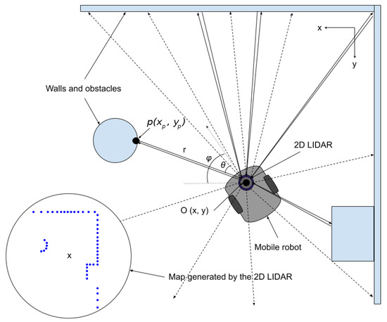
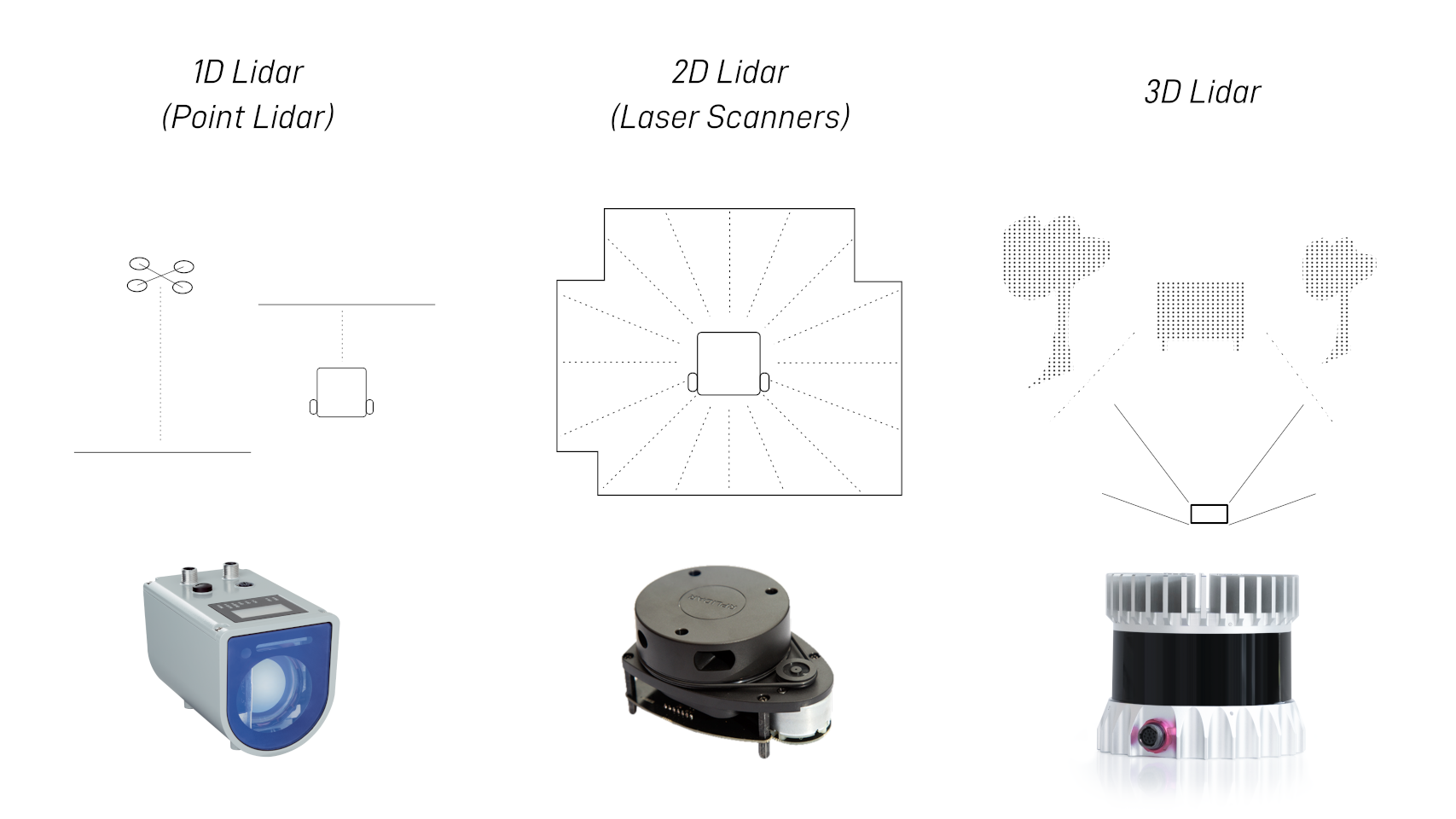
To connect and work with the Mijia STYTJ02YM LDS lidar sensor (model MVXVC01-JG) on an Arduino, note that this is a repurposed component from a robot vacuum cleaner. It uses laser triangulation for 360-degree distance scanning and is compatible with similar low-cost LIDARs like the Xiaomi LDS series. The process involves hardware wiring, motor control (since the sensor doesn't have built-in speed regulation), and software to read the UART data stream. These sensors typically operate at 5V and require an external power source capable of at least 0.37A.
Required Components
- Arduino board (e.g., Uno, which runs at 5V; for 3.3V boards like ESP32, use a logic level shifter for the TX line).
- MVXVC01-JG LIDAR sensor (available as a spare part from sites like AliExpress or Amazon).
- External 5V power supply (the Arduino's 5V pin may not provide enough current for sustained operation).
- Motor driver (e.g., simple NPN transistor like 2N2222 or an H-bridge module like L298N) for controlling the DC motor speed via PWM.
- Capacitors (e.g., 100nF ceramic) to bypass motor commutator arcing (place across motor terminals for noise reduction).
- Jumper wires and breadboard.
- Optional: Adapter board (e.g., from makerspet.com for similar LDS02RR models) if you want plug-and-play motor control and UART interfacing.
- Optional: Logic level shifter (if using a 3.3V microcontroller).
Pinout
The MVXVC01-JG uses a 5-pin JST-XH connector (common for these vacuum LIDARs; confirm with a multimeter if yours varies, as some Xiaomi models have 7 pins with extras for motor or ground). The standard pinout is:
| Pin | Signal | Description |
|---|---|---|
| 1 | VCC | +5V power input |
| 2 | GND | Ground |
| 3 | TX | UART data output (from LIDAR to Arduino, 5V logic) |
| 4 | Motor | Direct connection to the DC motor (supply ~2.2-3.8V here for 240-420 RPM) |
| 5 | – | Unused (no RX for commands; sensor transmits only) |
If your sensor has a 7-pin connector, it may include duplicates (e.g., extra GND or motor pins). Pins are typically arranged from left to right when viewing the connector with the latch up.
Wiring to Arduino
- Power: Connect VCC to Arduino's 5V (or external 5V supply). Connect GND to Arduino GND.
- Data: Connect TX to an Arduino digital pin (e.g., pin 10) for SoftwareSerial input. If using a 3.3V Arduino, add a voltage divider (e.g., 1kΩ and 2kΩ resistors) or level shifter to step down from 5V to 3.3V.
- Motor: Do not connect directly to Arduino—use a driver:
- Connect the motor pin to the collector of an NPN transistor.
- Emitter to GND.
- Base to an Arduino PWM pin (e.g., pin 9) via a 1kΩ resistor.
- Or use an H-bridge module for better control.
- Add 100nF capacitors across the motor terminals to reduce electrical noise.
- Ensure the setup can supply stable power; the sensor draws varying current based on motor speed.
The sensor starts transmitting data once the motor spins at the target RPM (240-420). Use PWM on the motor pin to adjust voltage/speed (e.g., analogWrite(9, 150) for ~3V). Monitor RPM from the data stream and tune accordingly.
Software Setup
Use the Arduino IDE. Install the SoftwareSerial library if needed (it's built-in).
Protocol Details
- UART: 115200 baud, 8-N-1 (8 data bits, no parity, 1 stop bit).
- The sensor streams frames with health (RPM) or measurement data (angles, distances, quality).
- No commands sent to the sensor (no RX needed); it auto-streams when spinning.
- Each full rotation (~360 degrees) is split into ~15 frames, each covering ~24 degrees with variable samples.
- Distances are in mm (scaled by 0.25), angles in degrees.
Example Arduino Code
This code reads the UART stream, decodes frames, and prints RPM, angles, and distances to the serial monitor. Adjust PWM to hit the RPM range.
#include <SoftwareSerial.h>

SoftwareSerial lidarSerial(10, -1);  // RX on pin 10, no TX needed
const int motorPwmPin = 9;           // PWM pin for motor control

uint8_t buffer[256];
uint8_t idx = 0;

void setup() {
  Serial.begin(115200);
  lidarSerial.begin(115200);
  pinMode(motorPwmPin, OUTPUT);
  analogWrite(motorPwmPin, 150);     // Start motor at ~3V; adjust for 240-420 RPM
}

void loop() {
  if (lidarSerial.available()) {
    buffer[idx++] = lidarSerial.read();
    if (idx >= 3) {  // Header (0xAA) + length (2 bytes)
      uint16_t len = (buffer[1] << 8) | buffer[2];
      if (idx >= len + 3) {  // Full frame received
        processFrame(buffer, len);
        idx = 0;
      }
    }
  }
}

void processFrame(uint8_t* frame, uint16_t len) {
  if (frame[0] != 0xAA) return;  // Invalid header

  uint8_t cmd = frame[5];
  uint16_t payloadLen = (frame[6] << 8) | frame[7];

  // Verify CRC (simple cumulative sum)
  uint16_t crc = 0;
  for (uint16_t i = 0; i < 3 + payloadLen; i++) {
    crc += frame[i];
  }
  uint16_t receivedCrc = (frame[3 + payloadLen] << 8) | frame[4 + payloadLen];
  if (crc != receivedCrc) return;  // Bad frame

  if (cmd == 0xAE) {  // Device Health
    uint8_t rpmScaled = frame[8];
    float rpm = rpmScaled / 3.0;
    Serial.print("RPM: ");
    Serial.println(rpm);
    // Adjust PWM here if RPM is out of 240-420 range, e.g.:
    // if (rpm < 240) analogWrite(motorPwmPin, 180);
  } else if (cmd == 0xAD) {  // Measurement Data
    uint8_t rpmScaled = frame[8];
    float rpm = rpmScaled / 3.0;
    uint16_t startAngle = (frame[9] << 8) | frame[10];
    float startDeg = startAngle * 0.01;

    uint16_t sampleCount = (payloadLen - 5) / 3;
    Serial.print("RPM: ");
    Serial.print(rpm);
    Serial.print("  Start Angle: ");
    Serial.print(startDeg);
    Serial.println(" deg");

    for (uint16_t s = 0; s < sampleCount; s++) {
      uint16_t offset = 11 + s * 3;
      uint8_t quality = frame[offset];
      uint16_t distRaw = (frame[offset + 1] << 8) | frame[offset + 2];
      float distance = distRaw * 0.25;  // in mm
      float angle = startDeg + (24.0 / sampleCount) * s;

      Serial.print("Angle: ");
      Serial.print(angle);
      Serial.print(" deg, Distance: ");
      Serial.print(distance);
      Serial.print(" mm, Quality: ");
      Serial.println(quality);
    }
  }
}
Tips and Troubleshooting
- Motor Speed: The sensor needs consistent RPM for accurate data. Use the health frames to monitor and adjust PWM. Too low/high causes noisy or invalid readings.
- Power Issues: Use an external supply if the Arduino browns out. The motor can draw up to 300mA.
- Noise: Add capacitors to suppress motor interference, which can corrupt UART data.
- Testing: Open the Serial Monitor at 115200 baud to see output. The sensor should stream once spinning.
- Libraries: For advanced use (e.g., ROS integration), check the kaiaai/LDS Arduino library on GitHub, which supports similar models like LDS02RR/Delta-2G and may work with MVXVC01-JG.
- Variations: If your pinout differs (e.g., extra pins), probe with a multimeter (VCC/GND obvious; TX idles high). Some models need a start command ('b' via RX if present), but MVXVC01-JG typically doesn't.
- Safety: Avoid looking into the laser. Test in a dark room initially, as bright light can affect accuracy.
- Further Resources: Check GitHub repos like engineerm-jp/vacuum_robot_lidar for code variations, or forums like Reddit r/arduino for user experiences with vacuum LIDARs.
If the data stream doesn't appear, double-check wiring, baud rate, and motor spin. For visualization, you can extend the code to plot data in Processing or Python.
Here's a complete Python script to visualize the data from your Mijia STYTJ02YM (MVXVC01-JG) LDS lidar sensor in real-time using matplotlib in polar coordinates. This creates a classic radar-like scan view where distances appear as radii from the center, and angles span 360 degrees.
The script assumes:
- Your Arduino runs code similar to the previous example (printing parsed data like "Angle: X deg, Distance: Y mm" to Serial at 115200 baud).
- The Arduino connects to your PC via USB (e.g., COM3 on Windows or /dev/ttyUSB0 on Linux/Mac).
If your Arduino only forwards raw bytes, you can modify the script to parse them directly (commented alternative provided).
Requirements
Install with pip if needed:
pip install pyserial matplotlib numpyPython Script: Real-Time Polar Visualization
import serial
import matplotlib.pyplot as plt
import numpy as np
import re
import threading

# ----------------------- Configuration -----------------------
SERIAL_PORT = 'COM3'          # Change to your port, e.g., '/dev/ttyUSB0' on Linux/Mac
BAUD_RATE = 115200
MAX_DISTANCE = 6000           # Max range in mm (adjust based on your environment, typical ~5000-8000mm)
UPDATE_INTERVAL = 0.05        # Seconds between plot updates (lower = smoother but more CPU)

# For raw byte parsing (uncomment if Arduino forwards raw UART data)
# Otherwise, keep the text parsing below if Arduino prints human-readable lines

# ----------------------- Global data -----------------------
angles = []      # in degrees
distances = []   # in mm
lock = threading.Lock()

def read_serial():
    """Background thread to read and parse data from serial"""
    ser = serial.Serial(SERIAL_PORT, BAUD_RATE, timeout=1)
    pattern = re.compile(r"Angle:\s*([\d.]+)\s*deg,\s*Distance:\s*([\d.]+)\s*mm")

    print("Reading data from serial... Press Ctrl+C to stop.")
    while True:
        try:
            line = ser.readline().decode('utf-8', errors='ignore').strip()
            if not line:
                continue

            match = pattern.search(line)
            if match:
                angle = float(match.group(1))
                dist = float(match.group(2))

                # Filter invalid distances (0 or too large)
                if dist > 0 and dist < MAX_DISTANCE * 1.5:
                    with lock:
                        angles.append(np.radians(angle))  # Convert to radians for polar plot
                        distances.append(dist)

        except Exception as e:
            print(f"Serial read error: {e}")
            break

# ----------------------- Plot setup -----------------------
fig = plt.figure(figsize=(8, 8))
ax = fig.add_subplot(111, projection='polar')
ax.set_theta_zero_location('N')  # 0° at top (North)
ax.set_theta_direction(-1)       # Clockwise (standard for lidars)
ax.set_rlim(0, MAX_DISTANCE)
ax.grid(True)
ax.set_title("Mijia STYTJ02YM LDS Lidar Real-Time Scan", va='bottom')

line, = ax.plot([], [], 'o', markersize=4, alpha=0.7, color='cyan')

def update_plot(frame):
    with lock:
        if angles and distances:
            line.set_data(angles, distances)
            # Optional: clear old points after full scan (keep last ~1000 points)
            if len(angles) > 2000:
                global angles, distances
                angles = angles[-1000:]
                distances = distances[-1000:]
    return line,

# ----------------------- Start threads -----------------------
thread = threading.Thread(target=read_serial, daemon=True)
thread.start()

ani = plt.animation.FuncAnimation(fig, update_plot, interval=UPDATE_INTERVAL * 1000, blit=False)
plt.show()
How It Works
- A background thread reads the serial port continuously.
- It parses lines printed by your Arduino (e.g., "Angle: 45.2 deg, Distance: 1234 mm").
- Points accumulate and update the polar plot in real-time.
- The view shows a 360° radar sweep with obstacles as dots farther from the center.
Tips
- Adjust SERIAL_PORT to match your device (check Device Manager on Windows or ls /dev/tty* on Linux).
- For better performance, modify your Arduino code to print in a compact format (e.g., CSV: angle,dist\n) and change the regex accordingly.
- If data is noisy, filter low-quality points (add quality parsing if your Arduino prints it).
- For Cartesian view instead of polar, replace the plot with ax.scatter(x, y) where x = dist * cos(rad), y = dist * sin(rad).
Example Visualizations
Typical output from Xiaomi vacuum lidars looks like this (real-time polar scans):

Run the script while your lidar spins — you should see a live map of your surroundings! If you encounter issues (e.g., no data), check the serial monitor first to confirm output.
No comments:
Post a Comment